Jan. 22, 2025
There are many types of control valves, which are essential products for chemical companies. Today we bring you the principles and differences of a variety of directional control valves. The control valve is composed of two main assemblies: valve body assembly and actuator assembly (or actuator system), divided into four series: single-seat Series control valves, double-seat series control valves, sleeve series control valves, and self-operated series control valves. Variations of the four types of valves can lead to many different applicable structures, each with its own special applications, characteristics, advantages, and disadvantages.
The hydraulic valve is used to control the flow direction of the oil in the hydraulic system or adjust its flow and pressure. As a kind of hydraulic control valve, the directional control valve controls the flow direction of the oil by changing the flow channel. The one-way directional control valve is a directional control valve that only allows airflow to flow in one direction, such as a one-way valve, shuttle valve, Double pressure valve, etc. Reversing type directional control valve is a directional control valve that can change the direction of airflow, referred to as the reversing valve.

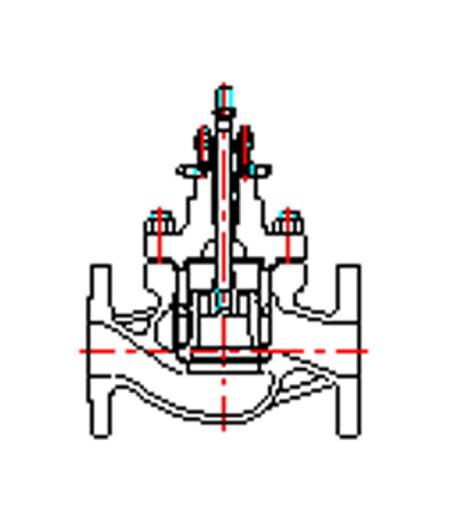
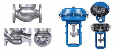
Guided Globe Control Valve
A one-way valve is a valve in which airflow can only flow in one direction, but not in the reverse direction. One-way valves are often combined with throttle valves to control the speed of actuators.
Composition: valve body, valve core, spring, etc.
Function: Only allow liquid flow to flow in one direction, and it will be blocked in the reverse direction.
Working principle: forward conduction, reverse cutoff.
Application: It is often installed at the outlet of the pump. On the one hand, it prevents the pressure shock from affecting the normal operation of the pump, and on the other hand, prevents the system oil from flowing back through the pump back to the tank when the pump is not working. It is used to separate the oil circuit to prevent high and low-pressure interference.
The hydraulic flow control check valve is a valve that can make the check valve flow in the reverse direction by controlling the fluid pressure. This kind of valve occupies an important position in the hydraulic support equipment of coal mining machinery. The difference between the hydraulic control check valve and the ordinary one-way valve is that there is an additional control oil circuit K. When the control oil circuit is not connected to the pressure oil, the hydraulic control check valve works like a normal one-way valve. It only flows from the oil inlet to the oil outlet, not reverse flow. When the control oil circuit has control pressure input, the piston mandrel moves to the right under the action of the pressure oil, and the one-way valve is opened with the mandrel to make the inlet and outlet ports connected. If the oil outlet is larger than the oil inlet, the oil can flow in the reverse direction.
Composition: ordinary one-way valve + small piston cylinder, internal and external leakage.
working principle:
a. When there is no control oil, it is the same as ordinary check valve
b. When the control oil is passed, it can flow in both forward and reverse directions.

The reversing valve is a directional control valve with more than two flow patterns and more than two oil ports. It uses the valve core to make relative movement in the valve body hole to make the oil circuit connect or cut off and change the oil flow direction. It is a valve that realizes the communication, cut-off, and reversal of hydraulic oil flow, as well as pressure unloading and sequential action control.
Classification of reversing valve:
According to the structure, it can be divided into a slide valve type, rotary valve type, and ball valve type. According to the number of main oil passages connected by the valve body, it can be divided into a two-way, three-way, four-way, etc. According to the working position of the valve core in the valve body, it can be divided into two positions, three positions, four positions, etc. According to the way of operating the spool movement, it can be divided into manual, motorized, electromagnetic, hydraulic, electro-hydraulic, etc.
The manual reversing valve is a directional control valve operated by a manual lever, which plays the role of reversing (changing the direction of liquid flow) and switching (turning on or cutting off the flow of liquid) in the hydraulic system.
The motorized reversing valve is also called the stroke valve, which is mainly used to control the stroke of the mechanical moving parts. The valve core is forced to move by means of the stop iron or cam installed on the workbench, thereby controlling the direction of the liquid flow.
The electromagnetic reversing valve uses electromagnet suction to push the spool to change the working position of the valve. It can change the direction of the control liquid flow, thereby changing the position of the hydraulic reversing valve. Since the hydraulic thrust for operating the hydraulic directional valve can be large, the main valve can be made large, allowing a large flow to pass. In this way, a smaller electromagnet can control a larger liquid flow.
Linear motion valves have a closure member that moves with a linear motion to modify the rate of flow through the valve. Linear motion valves are generally named for the shape of their closure member. Common linear motion valves include globe, gate, diaphragm and pinch valves.
Globe valves are so named for their globular shaped cavity around the valve seat area. The closure member of a globe valve is a plug with a flat or convex bottom that is lowered onto a matching horizontal seat located in the center of the valve. Raising the plug opens the valve, allowing fluid flow. Globe valves have good throttling characteristics but because the flow path is not linear they have a relatively high pressure drop across the valve. Globe valves are used in throttling and shut-off applications where this pressure drop is acceptable. The three primary body designs for globe valves are Z body, Y body and angle.
B. Gate Valve
The closure member of a gate valve is a flat face, vertical disc, or gate that slides down through the valve to block the flow. Gate valves are designed to operate in their fully open or fully closed position and therefore are found only in
flow shut-off applications. When fully open the disc is removed completely from the flow stream. This offers
virtually no resistance to flow when the valve is fully open, therefore gate valves operate with little pressure drop across the valve. Gate valves have very poor flow throttling characteristics and are not used for throttling purposes.
C. Diaphragm Valve
The closure member of a diaphragm valve is a flexible surface (the diaphragm) that is deformed. The main advantage of a diaphragm valve is that the stem seal is eliminated. Diaphragm valves are used mostly for shut-off service of slurries, corrosive or viscous fluids but may also be used in flow throttling applications as well.
Diaphragm valves may be used in pumping applications with a set constant pressure on the diaphragm. This allows flow to be stopped in the absence of a motive force (pump), but when a sufficient pressure is generated in the pipe to overcome the force on the diaphragm flow is allowed.
A pinch valve is similar to a diaphragm valve, however in a pinch valve the entire valve body is flexible and the closure member pinches the valve shut closing off flow. As a pinch valve has no internal obstructions it has a very low pressure drop and is well suited for applications of slurries or liquids with large amounts of suspended solids.
Rotary valves have a closure member that moves with a rotary motion to modify the rate of flow through the valve. Like linear motion valves, rotary motion valves are generally named for the shape of their closure member. Common rotary motion valves include ball, butterfly and plug valves.
The closure member of a ball valve is shaped like a ball with a port for fluid flow. A ball valve allows straight-through flow in the open position and shuts off flow when the ball is rotated 90 degrees. Because of their quarter turn
actuation and low pressure drop ball valves are commonly found in flow shut-off applications. Depending on the particular flow port configuration of the ball they may be used in flow throttling applications as well.
The closure member of a butterfly valve is a circular disc or vane with its pivot axis at right angles to the direction of flow in the pipe. Like ball valves, a butterfly valve allows straight-through flow in the open position and shuts off flow when the ball is rotated 90 degrees. Because of their quarter turn actuation and low pressure drop butterfly valves are commonly found in flow shut-off applications. Unlike ball valves, butterfly valves are generally not used for flow
throttling applications. The advantage of a butterfly valve over a ball valve is its relative compactness.
D. Plug Valve
The closure member of a plug valve is a cylindrical or tapered cylindrical shaped plug with a flow port.
Like a ball valve, a plug valve allows straight-through flow in the open position and shuts off flow when the ball is rotated 90 degrees. Like ball valves, plug valves are found mostly in flow shut-off applications. However plug valves are available in much larger sizes that ball valves.
The above information is provided by the valve supplier. If you have any questions, please contact us.
Headquarter Add.: SUPCON Park, No.309 Liuhe Road, Binjiang District, Hangzhou, 310053, China.
Tel.: +86 571 8111 9774
Fax: +86 571 8111 9737
E-mail: [email protected]
