Oct. 19, 2020
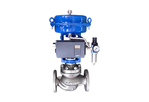
Pnuematic regulating valve is one of industrial process control instruments, widely used in petroleum, chemical, electric power, metallurgy, and other industrial enterprises. Regulating a valve is an indispensable regulating system in chemical production and an important part of the industrial automation system.
Working principle:
The pneumatic control valve is powered by compressed air, and the cylinder is the actuator. It drives the valve with the help of accessories such as electric valve positioner, frequency converter, solenoid valve, holding valve, etc., realizes switch or proportional adjustment, and accepts industry. The control signal of the automatic control system completes the adjustment of the pipeline medium: the adjustment of the flow rate, the holding valve, and other accessories. Various technical parameters such as pressure and temperature. The pneumatic control valve has the characteristics of simple control, fast response, inherent safety, etc., and no additional explosion-proof measures are required.
Working principle of the pneumatic control valve
The pneumatic control valve is usually composed of a pneumatic actuator and control valve connection installation and debugging. A pneumatic actuator can be divided into single-acting and double-acting. Single-acting actuators have return springs, while double-acting actuators have no return springs. . Among them, the single-acting actuator can automatically return to the initial open or closed state of the valve when it loses its origin or suddenly fails.
Pneumatic control valves are divided into two types, namely, normally open and normally closed, according to the active form. The pneumatic control valve is normally open or closed by the positive and negative effects of the actuator and the valve structure. The different assembly methods are realized.
Pneumatic regulating valve mode of action
The air-open type (normally closed type) means that when the air pressure on the membrane head increases, the valve moves in the direction of increasing opening. When the upper limit of the input air pressure is reached, the valve is fully open. Conversely, when the air pressure decreases, the valve moves in the closing direction. When there is no air input, the valve is fully closed. Gu usually we call the air-to-open control valve a fault-closed valve.
The air-to-close type (normally open type) moves in the opposite direction to the air-to-open type. When the air pressure increases, the valve moves in the closing direction; when the air pressure decreases or does not, the valve moves in the opening direction or fully open. Gu usually we call the air-to-close control valve a fail-open valve.
The choice of air-on and air-off is based on the safety of process production. When the air source is cut off, whether the regulating valve is in the closed position or the open position is safe.
For example, for the combustion control of a heating furnace, a regulating valve is installed on the fuel gas pipeline, and the fuel supply is controlled according to the temperature of the furnace or the temperature of the heated material at the outlet of the heating furnace. At this time, it is safer to choose an air-open valve, because once the air source stops supplying, it is more appropriate for the valve to be closed than for the valve to be fully open. If the gas supply is interrupted and the fuel valve is fully opened, it will cause the danger of overheating. Another example is heat exchange equipment cooled by cooling water. The hot material exchanges heat with the cooling water in the heat exchanger to be cooled. The regulating valve is installed on the cooling water pipe. The temperature of the material after the heat exchange is used to control the amount of cooling water. When the air source is interrupted, the regulating valve should be in the open position, and it is safer to use the air-closed (ie FO) regulating valve.

Regulating Valve
Pneumatic control valve installation principle
(1) The installation position of the pneumatic control valve must be at a certain height from the ground, and a certain space must be left above and below the valve for valve disassembly and repair. For regulating valves equipped with pneumatic valve positioners and handwheels, it is necessary to ensure convenient operation, observation, and adjustment.
(2) The regulating valve should be installed on a horizontal pipeline and vertical to the pipeline up and down. Generally, it should be supported under the valve to ensure stability and reliability. For special occasions, when the regulating valve needs to be installed horizontally on a vertical pipeline, the regulating valve should also be supported (except for small-diameter regulating valves). When installing, avoid adding additional stress to the regulating valve).
(3) The working environment temperature of the regulating valve should be (-30~+60) relative humidity not more than 95% 95%, relative humidity not more than 95%.
(4) There should be straight pipe sections at the front and rear positions of the regulating valve, with a length not less than 10 times the pipe diameter (10D), to avoid that the straight pipe section of the valve is too short to affect the flow characteristics.
(5) When the caliber of the regulating valve is different from that of the processing pipeline, a reducing pipe should be used for the connection. When installing the small-diameter regulating valve, a threaded connection can be used. The fluid direction arrow on the valve body should be consistent with the fluid direction.
(6) To set a bypass pipeline. The purpose is to facilitate switching or manual operation and to overhaul the regulating valve without stopping the machine.
(7) The control valve must be thoroughly cleaned of foreign matter in the pipeline before installation, such as dirt, welding slag, etc.
Previous: Type of Control Valve
Headquarter Add.: SUPCON Park, No.309 Liuhe Road, Binjiang District, Hangzhou, 310053, China.
Tel.: +86 571 8111 9774
Fax: +86 571 8111 9737
E-mail: [email protected]
